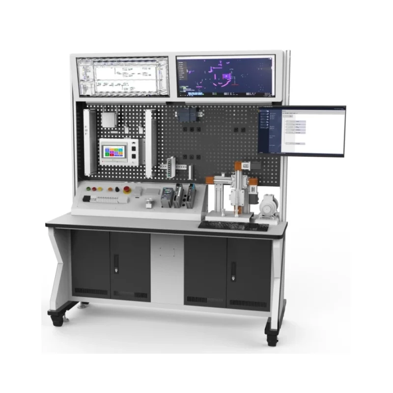
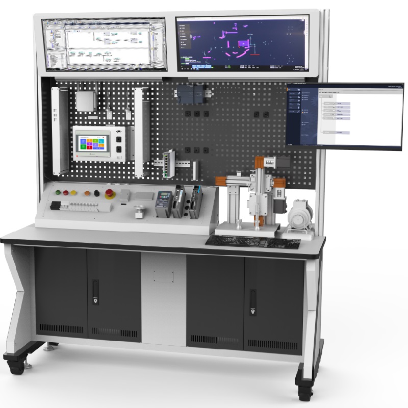
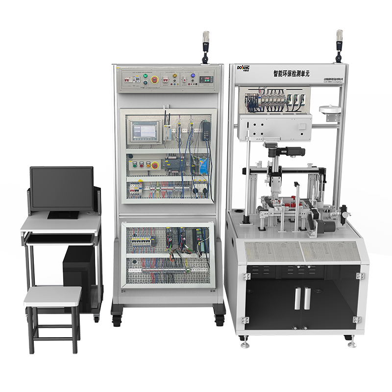
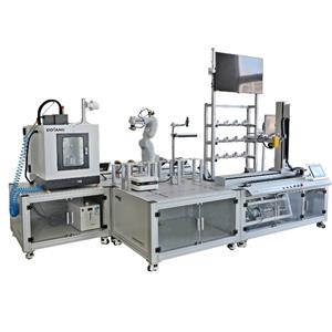
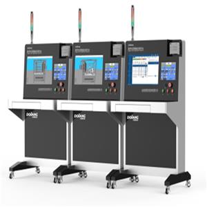
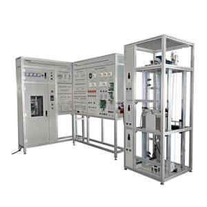
DLIOT-471 Industrial Automation Network Integration Training System

1. Realize the interconnection and intercommunication of production and manufacturing equipment. The communication network connects field devices, controllers, HMI, monitoring systems and enterprise management systems. It is the information transmission channel in the industrial production system and plays an important role in the stability and reliability of the industrial production system. At present, industrial network technology is developing in the direction of modern network technology——industrial Ethernet technology and industrial Internet. The use of civilian common Ethernet technology cannot guarantee the integrity of industrial Ethernet implementation, and it is difficult to meet the reliability requirements of industrial-grade communication. Therefore, special training equipment is required
1. Overview
The overall structure and functions of the Industrial Internet training room
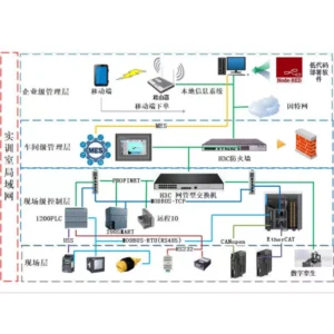
The system is based on the Siemens four-network structure:
The first layer is “enterprise management”, which conducts overall scheduling and data management of the entire network system, and intelligent production management through mobile terminals and server terminals.
The second layer is the “operation level layer”, with MES as the main control system, real-time monitoring and operation of data through the host computer.
The third layer is the “control layer”, which is mainly composed of 1200PLC, 200SMART, H5UPLC, smart touch screen, etc. It is used for the analysis, calculation, processing and logic control functions of the bottom data, and realizes the upload and release of data;
The fourth layer is the “on-site layer”, which is mainly composed of remote station instruments, servos, frequency converters, sensors and other hardware as well as 3D virtual workstations to simulate the production process of the production line.
Different levels are connected by network management switches with different functions, which have strong network protection functions!
The network structure topology of the industrial automation network training platform is shown in the following figure:
2. Technical Parameter
1. Input power: three-phase five-wire ~380V±10% 50HZ
2. Leakage protection: I△n≤30mA, t≤0.1S
3. 380V three-phase five-wire output power supply
4. 24V DC power output, analog signal source
5. Emergency stop button, power supply indication, power supply indication
6. Protection against power failure and wrong power on
7. Working environment: Temperature -10°C~+40°C Relative humidity <85% (25°C) Altitude <4000M
8. Equipment Workbench
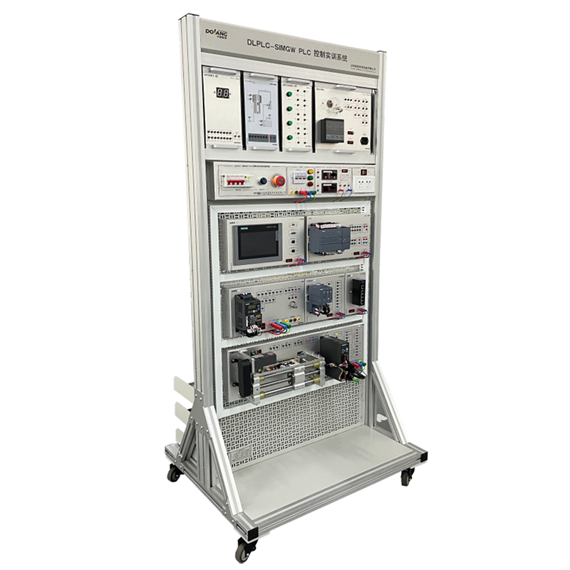
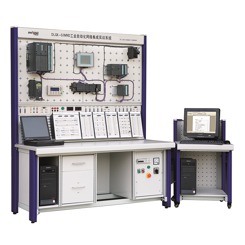
Constructed of industrial aluminum profiles, with wheels at the bottom, the overall equipment is light and strong, generous and beautiful; the design conforms to the principle of ergonomics, and the operation and use are more convenient. It is made of sheet metal and industrial aluminum profiles, which is atmospheric and beautiful.
The mesh board or panel structure is adopted, which is ergonomically designed. It should have a multi-functional power box to ensure power supply. It is required that the components be arranged on the mesh board or panel, which is intuitive and reusable.
3. Completable Training Content
1. Experiments that enterprise management can complete
1.1, Node-RED software operation experiment
1.2. Mobile phone order management experiment
2. Experiments that can be completed by the workshop level management system
2.1. Application of MES system
2.2. MES server configuration experiment
2.3. Network configuration experiment
2.1, Firewall network quick configuration
2.2. Firewall access mode configuration
2.3, firewall anti-fraud configuration
2.4, IP address scanning
2.5. Defense in depth intrusion configuration
2.6, ANT technology configuration
2.7, VPN configuration
2.8. Industrial software application
3. Experiments that can be completed by the field-level management system
3.1. Based on PROFINET bus communication technology
3.2. Communication technology based on TCP/IP protocol
3.3. Communication technology based on S7 protocol
3.4. Communication technology based on the Internet of Things
3.5. Switch network configuration (Ethernet, VLAN network)
3.6, ARP intrusion detection configuration
3.7. Port management
3.8, switch system management settings
3.9. Application layer filtering experiment
4. Experiments that can be completed at the field level
4.1. Communication technology based on EtherCAT bus
4.2. MODBUS-RTU communication based on RS485 interface
4.3. MODBUS-RTU communication based on RS485 interface
4.4. Free port protocol communication based on RS485 interface
4.5. Communication technology based on USS protocol
4.5. Application of MODBUS-ASCII protocol
4.6. Digital twin simulation application based on PROFINET protocol
4.7. Network configuration based on each communication protocol
4.8. Axis control experiment based on EtherCAT communication protocol
4.9. Axis control experiment based on CANopen communication protocol

